C64 PAL to RGB Adaptor
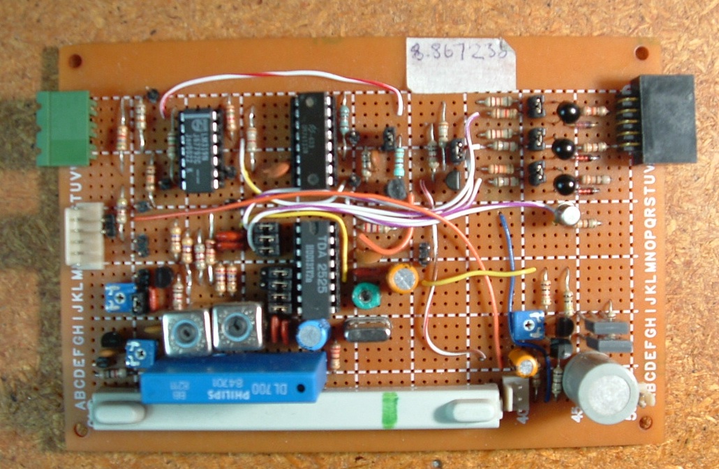
This is a circuit I built to decode the PAL video output from a
Commodore 64 for display on an RGB monitor. It's based on some parts I
salvaged from and old TV set, in particular a TDA2525 PAL demodulator
chip, the luma and chroma delay lines, and a couple of inductors.
Click photos to enlarge.
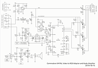
Schematic
Click to enlarge.
How it Works
The following assumes some familiarity with the PAL colour video encoding system. If you're interested, I've written a brief summary here based on what I've learned from my googling and experiments.
Inputs from the C64
I chose to use the separate luminance and chrominance signals provided
by the C64 rather than the composite video output, since I need them
separated anyway.
Sync Separator
The first thing I had to do was separate the sync pulses from the video
signal and generate a burst gating signal. Sync separation is done by
comparator U1. The sync part of the luminance signal from the C64
ranges from about 0V to 0.3V, so the comparator needs to switch at a
threshold of about 0.15V. R1 and R2 raise this a little so that it is
within the input range of the LM319.
Monostable U2 is triggered by the trailing edge of the sync pulse and
generates a burst gate pulse lasting about 2µs. Q3 is a level shifter
that produces the 0-12V pulse needed by the TDA2525.
The separated sync signal is also taken to Q8 for driving the monitor's
sync input.
The TDA2525
I wasn't able to find a datasheet for that exact chip, but I found one
for the TDA2522, which appears to
be very similar. The datasheet is a
bit light on usage details, but I found schematics for a couple of TV
receivers that used it, and between those and the datasheet I was able
to figure it out.
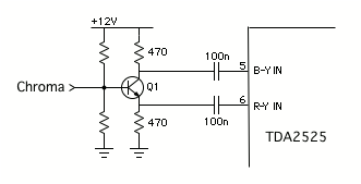
The TDA2525 has separate inputs for the B-Y and R-Y demodulators at
pins 5 and 6. How these are used depends on whether you're using a PAL
delay line or not. I decided to try doing without one at first, in the
interests of simplicity, to see what would happen. When used this way,
pins 5 and 6 need to be fed with the same chrominance signal but in
opposite phases. So the first version I built used a phase splitter,
like this:
C4, C5, C6 and R19 form a filter network for the phase-locked loop. I
don't know any details of how it works, I just copied it directly from
the TV circuit. C7 and C8 and pin 13 are concerned with automatic
colour control. In a TV receiver, pin 13 would be used to control the
gain of the chrominance amplifier, but I don't need this, so I left it
unconnected.
Crystal X1 provides an 8.86MHz clock which is divided down inside the
chip to the 4.43MHz PAL subcarrier frequency. Trimmer VC1 can be used
to fine-tune the frequency, but I found it would lock on quite happily
in almost any position, so a fixed capacitor of 10pF or so could
probably have been used just as well.
Pin 16 is designed to have a capacitor connected to control the time
constant of the colour killer. In a TV receiver, this disables the
colour outputs when no colour information is present, so that
monochrome signals are decoded without random colour artifacts. But I
don't need a colour killer because the C64 will always be providing a
chrominance signal, so as per the datasheet I connected pin 16 to
ground through a 2.7k resistor, which disables the colour killer.
Decoded R-Y, G-Y and B-Y colour signals come out at pins 1-3. Luminance
(Y) is added to these by resistor network R21-R26 to give R, G and B,
which are buffered by Q5-Q7 and sent to the monitor. Diodes D1-D3 are
included because, due to the DC offsets of the various inputs to the resistor
network, the black level comes out a little too high
otherwise.
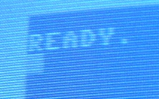
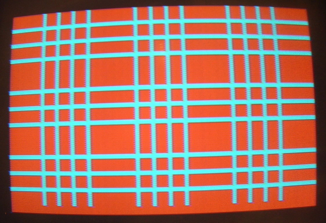
Chrominance delay line
I was hoping that a chrominance delay line wouldn't be needed, but that
turned out not to be the case. The problem can be seen here, where
there is a noticeable difference in brightness between consecutive
lines.

Looking at the signals with a scope, there didn't seem to be any
difference in the amplitude of the chrominance from one line to the
next, which meant there must have been a slight phase shift on
alternate lines. From what I've read, it seems that this is a known
problem with the PAL version of the C64.
Since phase errors are what the PAL system is designed to address, next
I tried the full PAL decoding arrangement incorporating a chrominance
delay line. The phase splitter was replaced by a chrominance amplifier
(Q1, Q2) to compensate for losses in the delay line (DL2). (You can see
vestiges of the phase splitter in the fact that the collector resistor
of Q1 is actually two resistors. The points labelled PSR and PSB are
the old phase splitter outputs; I left them in place and installed
headers H1 and H2 so that I could switch the delay line in and out with
jumpers for comparison purposes.)
The output
from the delay line is combined with the output from the chrominance
amplifier coming via VR1, C3, R13 and R14. The two ends of the delay
line output have opposite phases, so the chrominance from the previous
line is added to the current line at the B-Y input and subtracted from
it at the R-Y input. This achieves the extra flip along the R-Y axis
needed to cancel phase errors.
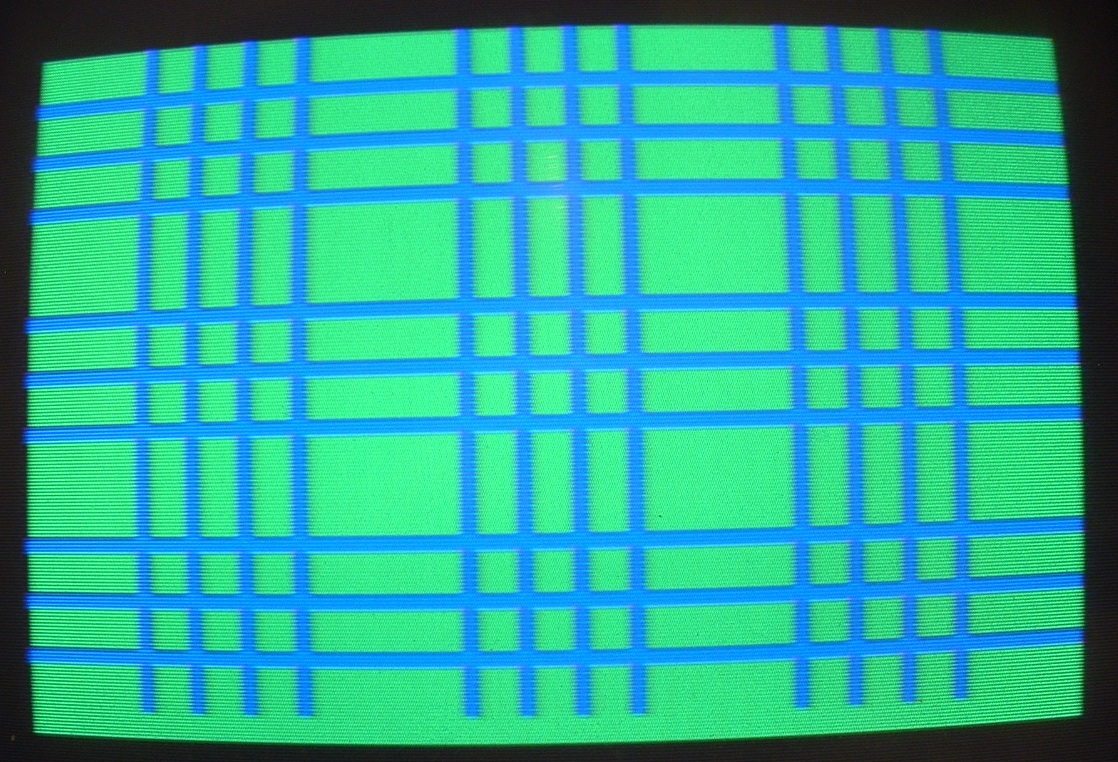
VR2 needs to be adjusted so that the amplitudes of the direct and
delayed chrominance at the B-Y and R-Y inputs are equal. One way to do
this is to look at a screen full of solid colour and adjust it until
all the lines look the same. During my initial attempts at this, I was
able to get the blue of the C64's default colour scheme looking fairly
good:


However, I wasn't able to get it right for all colours at the same
time. When blue was balanced correctly, red wasn't, and vice versa.
While playing around with it, I also thought of another way to perform
the adjustment. The default background colour seems to be pure blue, so
the R-Y component is zero and the chrominance consists entirely of B-Y.
Since B-Y is unchanged by the phase reversal of R-Y on alternate lines,
the direct and delayed chrominance at the R-Y input should have
opposite phases and cancel completely. So I should be able to put the
scope on the R-Y input and adjust VR2 for minimum amplitude.
When I tried this, I found that I could get it down nearly to zero on
odd lines, but then it would be significantly non-zero on even lines.
Or, I could compromise and get the amplitude roughly equal on all
lines. Visually, this corresponded to either having odd lines pure blue
and even lines somewhat purple, or having all lines the same shade of
slightly purplish blue. While the latter wasn't really noticeable, it
was still a compromise and had worse effects on most of the other
colours.
Thinking about what might be going wrong, it occurred to me that proper
cancellation relies on the chrominance being delayed for a whole number
of subcarrier cycles to a fairly high accuracy, and I began to doubt
whether the delay line was made that accurately. Some careful scope
measurements seemed to show that there was a significant phase
discrepancy between the input and the output of the delay line. It
didn't seem like it could ever work properly unless there were some way
of fine-tuning the delay.
Then I turned my attention to L1 and L2. Until then, I hadn't really
known what their purpose was. I had tried including or excluding them,
and it didn't seem to make much difference either way, except for a
slight change in the amplitude of the delay line output. Later I found
that without them I couldn't get the VR2 adjustment anywhere near
right, so they did seem to be necessary, even if I didn't know exactly
why. But I had only been thinking about their effect on the amplitude,
not the phase.
Now, I began to wonder whether their true purpose included adjusting
the phase of the delayed signal to compensate for inaccuracies in the
delay. Up to then I hadn't tried adjusting them, reasoning that they
had already been adjusted for the circuit they came out of, so it would
be best to leave them alone. But perhaps that reasoning was flawed,
since my version of the circuit has a different layout with different
stray capacitances and inductances, etc. So I scoped the delay line
output and tried moving the slugs. I found that I could indeed shift
the phase somewhat, particularly with L2. By fiddling with both L2 and
VR2 I was able to get it so that all the colours looked reasonably
good. Progress!
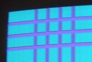
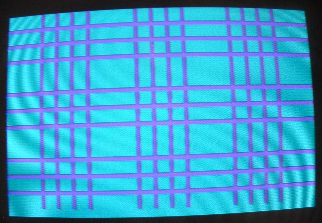
Luminance delay line
I wasn't quite out of the woods, though. The following was supposed to
be purple lines against a cyan background. Instead it came out as
adjacent grey and purple lines in the vertical direction.

This one was easier to fix, though. I knew immediately what was causing
the problem -- I hadn't included a luminance delay line. This provides
a small delay to compensate for the fact that the chrominance goes
through more processing than the luminance.
On the schematic it's DL1. R5 and R6 provide impedance matching to
prevent reflections (I tried it without them, and it was terrible). Q4
buffers the output for driving the luminance addition resistor network.
The result was a big improvement:
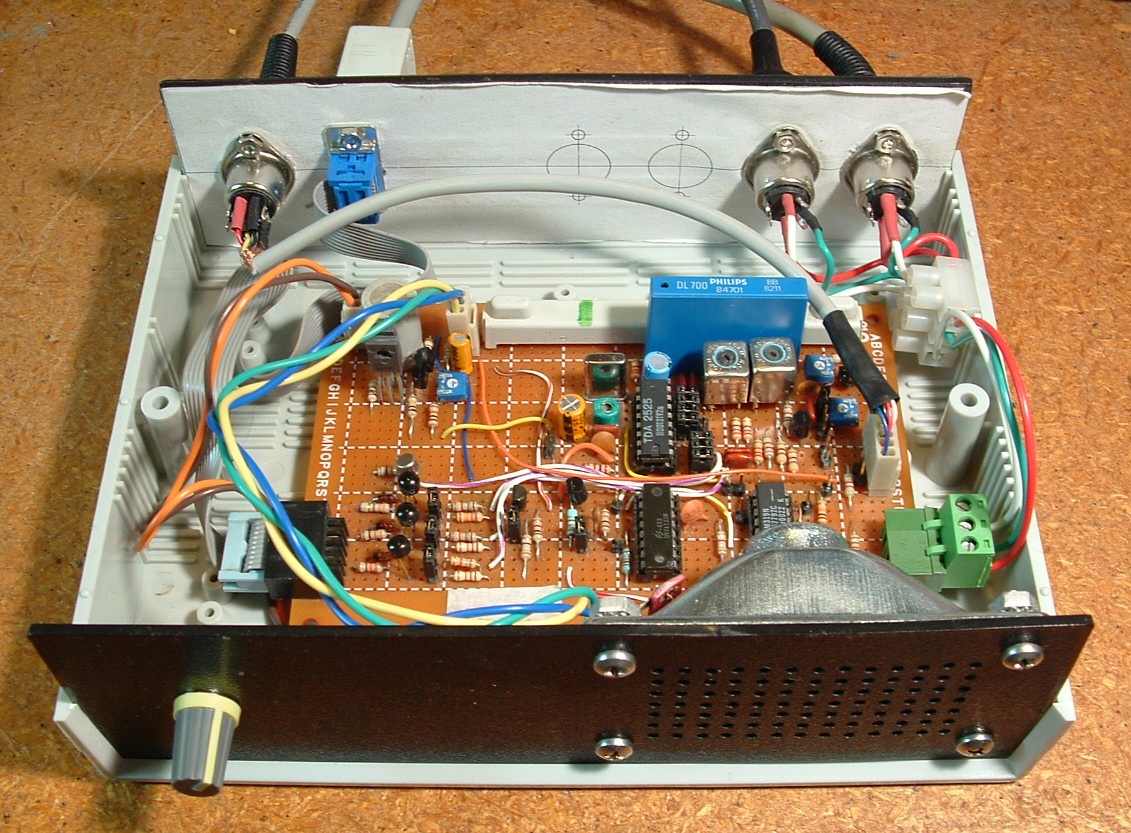
Audio
I had some spare space on the board and room in the box, so I added an
audio amplifier (Q9-Q12) and a small loudspeaker. That part was much
easier to get working!
Final Results
Here are some more screenshots - click to enlarge.
It's not perfect. Some colour combinations still look a bit raggedy,
particularly with narrow vertical lines.
I suspect it's possible to do better, but I'm not sure. I haven't seen
a real C64 running with a TV or monitor with composite video input, and
I don't have one around to try it with. I've seen screenshots of C64s
that look quite a lot better, but they're probably NTSC, so I'm not
sure how good a PAL C64 is capable of looking. In any case, I'm out of
ideas for the moment, and I feel I've spent enough time on something
that I'll only be using occasionally. If I get a brainstorm I may come
back to it later.
If anyone out there with experience of things like this, and who
actually knows what they're doing, has any ideas, free free to let me
know!
greg.ewing@canterbury.ac.nz

