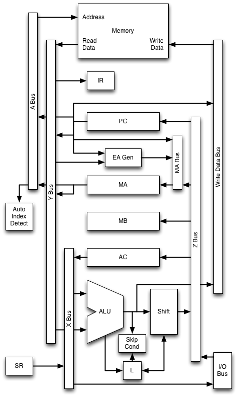
Data Paths
The following diagram shows a high-level view of the data paths
connecting the machine's registers, ALU, memory and I/O devices.
The registers are:
- PC - Program Counter, 12 bits
- MA - Memory Address, 12 bits
- MB - Memory Buffer, 12 bits
- AC - Accumulator, 12 bits
- L - Link, 1 bit (holds the carry from add and rotate operations)
- IR - Instruction Register, 3 bits (holds the major opcode field
of the currently executing instruction)
- SR - Switch Register, 12 bits (the data switches on the front
panel, not really a register)
Other functional units connected to the data paths include:
- Main Memory (up to 4096 x 12 bit words)
- ALU - carries out AND, addition and complementing operations
- Shifter - carries out rotation operations
- Effective Address Generator - calculates the address specified by
a memory reference instruction
- Auto-Index Detector - determines when a location in the address
range 010-017 is being addressed
- Skip Condition Evaluator - determines when the condition of a
skip instruction is true
- I/O devices - via the I/O bus
The data paths consist of four main buses:
- A Bus
- Carries the address of the memory location being read or
written. It is fed by the PC or MA register.
- X Bus
- Carries the X input to the ALU. It can be fed from AC or with
zeroes. It also provides output data to I/O devices.
- Y Bus
- Carries the Y input to the ALU. It can be fed from PC or MA, or
with data read from the memory.
- Z Bus
- Carries the output from the ALU. It can provide data to any of
the four main registers, to write to the memory, or to send to an I/O
device. It can also be fed from SR.
The main memory has separate read and write data connections to permit
read-modify-write operations to be carried out in a single cycle.
The MA register is fed by its own bus, the MA Bus. This can accept data
from the PC, the Effective Address Generator, or the Z Bus.
The Effective Address Generator receives inputs from the address field
and page selection bit of the instruction word being read from memory,
and the current page numberfrom the PC.
The L register is not connected directly to any of the buses, but
communicates with the ALU.
There are some other connections to the registers not shown here.
Outputs from IR and MB are connected to the instruction decoder, MB
supplies the device selector and operation code to the I/O bus, and
there are connections from PC, MA, MB, AC and L to the front panel
display lamps.