Machine Timing and Major States
Major States
Like the original PDP-8, the PDP-8/R has three main states that it can
be in during any clock cycle, Fetch, Defer and Execute.
Most
instructions consist of a Fetch cycle followed by an Execute cycle.
When a memory reference instruction uses indirect addressing, a Defer
cycle occurs between Fetch and Execute.
There are also three additional states, Load Address, Deposit
and Examine, that were
not present in the original. These states are entered in response
to pressing the corresponding buttons on the front panel while
the machine is halted. The machine then runs for one cycle and halts
again.
The following diagram shows the possible transitions between the major
states.
The original PDP-8 also had some additional states for handling DMA
requests. I have not implemented these yet, but I may add them later if
I decide to provide DMA facilities. I may also add another state for
interrupt servicing if I decide to provide an interrupt facility.
Timing
In the original PDP-8, each machine cycle was divided into four time
periods. The 8/R has a simpler timing structure, with each cycle
consisting of a single time period. The master clock provides two
signals: CLOCK, which has a 50% duty cycle, and CLOCKP, which consists
of a
brief pulse at the end of each clock cycle. The CLOCKP signal is the
one used for
most timing functions, being used to strobe data into registers and
memory locations.
Starting and halting the machine is accomplished by enabling and
disabling the master clock under direction of the Run Control
flip-flop. When the Start or Continue button is pressed, Run Control is
set and the master clock begins generating clock signals. When Run
Control it
is cleared, the master clock is stopped.
The Run Control flip-flop can be cleared in a variety of ways:
- Reaching the end of an instruction during which the Stop button
was pressed
- Reaching the end of an instruction while the Single Instruction
switch is turned on
- Reaching the end of a cycle while the Single Step switch is
turned on
- Reaching the end of a Deposit or Examine cycle
- Executing a HALT instruction
Clearing of Run Control is synchronised with the clock, so that once
started, the clock always generates full cycles and
never stops in the middle of a cycle.
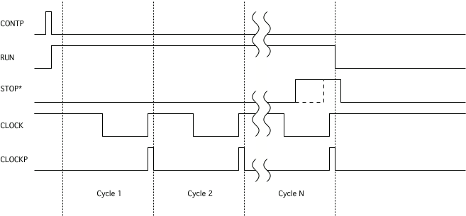
The following diagram shows the timing relationships between the timing
and clock control signals. CONTP* is a pulse produced by pressing any
of the
Start, Continue, Load Address, Deposit or Examine buttons. RUN is the
output of the
Run Control flip-flop, and is on whenever the machine is running. STOP*
is a signal generated by a variety of internal sources; it causes the
clock to
stop at the end of the current cycle.