Building Blocks
Here are schematics of some frequently-used subcircuits.
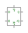
D Flip-Flop
This is technically a transparent D latch, although in most cases I am
using it as an edge-triggered flip-flop by connecting the Enable input
to a pulse signal such as CLOCKP.
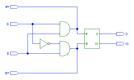
Direct set and reset are also available by making wired-OR connections to the S* and R* inputs.
Symbol
|
Schematic
|
 |
 |
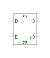
D Flip-Flop with Isolated Set and Reset
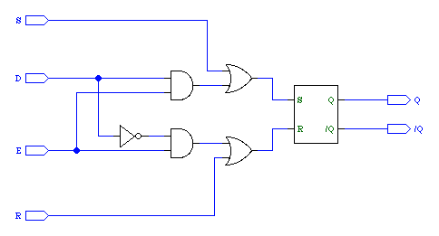
A variation of the D flip-flop that does not use wired-OR connections for the Set and Reset inputs.
Symbol
|
Schematic
|
 |
 |
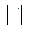
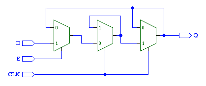
Edge-Triggered D Flip-Flop with Enable
I developed this flip-flop circuit after encountering reliability
problems with some types of logic elements in Redpower prerelease 4d.
The D input is transferred to the Q output on the rising edge of the
clock provided E is on.
Symbol
|
Schematic
|
 |
 |