Master Clock Circuits
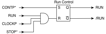
The Master Clock circuitry includes the Run Control flip-flop, the master clock itself, and the Stop Flag flip-flop.
The Run Control flip-flip is set by CONTP*, and reset at the end of the
current clock cycle when STOP* is asserted. Its outputs produce the
complementary RUN and /RUN signals. The reset signal is gated with RUN
so that it is removed as soon as the flip-flop is reset.
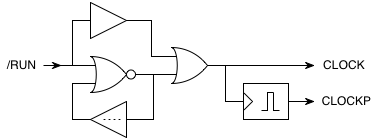
The following circuit forms the master clock. It is based on an
inverter and a delay element connected in a loop, with a NOR gate used
as the inverting element so that the clock can be turned on and off.
When the control input is off, the clock runs, and when on, the clock
is disabled. The OR gate at the output blocks spurious signals after
disabling and ensures that the clock turns off cleanly. The CLOCK
output idles in the "on" state when the clock is disabled. A pulse
former generates the CLOCKP signal from the rising edge of CLOCK
occurring at the end of each cycle.
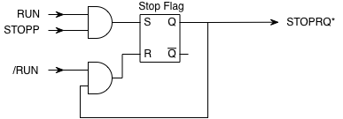
The Stop Flag flip-flop synchronises the STOPP pulse produced by
pressing the Stop button. When STOPP occurs and the machine is running,
the Stop Flag is set. This asserts STOPRQ*, which in turn asserts STOP*
when the Execute cycle of the current instruction is reached (the
gating for this is part of the Major State circuit). When the machine
stops, the Stop Flag is reset by /RUN. The reset signal is gated with
the Q output of the Stop Flag so that it is removed as soon as the flag
is reset.