Before building any hardware, I'm going to model the CPU using Logisim
to test out the design.
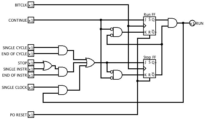
Here's the first part, the Run Control circuit. Its purpose is to take
signals from the front panel controls for starting and stopping the
machine, together with some signals derived from the machine's state,
and generate a RUN signal that is active whenever the machine should be
running. This signal will be used to gate BITCLK pulses to the rest of
the machine, so its transitions need to be aligned with BITCLK period
boundaries.
CONTINUE and STOP will be connected to pushbuttons on the front panel.
(In the original EDSAC, CONTINUE was named "Reset", but I've renamed it
to avoid confusion with the power-on reset signal.)
SINGLE CYCLE, SINGLE INSTR and SINGLE CLOCK are mode-selection
inputs that will be connected to switches of some kind. END OF CYCLE
and END OF INSTR are internal signals that will be active during the
last clock period of a short word cycle or a complete instruction
respectively.
At power up, the PO RESET signal resets both flip flops so that RUN is
initially inactive.
When the CONTINUE button is pressed, on the next rising edge of BITCLK
the Run FF becomes set and RUN becomes active. It remains active until
the Stop FF is set, which occurs at the next rising BITCLK edge for
which one of the following things is true:
SINGLE CLOCK mode is selected.
SINGLE CYCLE mode is selected and it is the last clock period of a short word cycle.
The STOP button is pressed or SINGLE INSTR mode is active, and it is the last clock period of an instruction.
When the Stop FF is set, it deactivates RUN via the AND gate. This
condition persists until both CONTINUE and STOP are released, whereupon
both flip flops are reset and the machine is ready to be started again.