Front Panel Load Address Operation
The way the data paths are set up, the easiest way to get a value from
the switches to the PC is to go through the instruction register.
However, I can't load the whole instruction register in the middle of a
microcode sequence, because that would mess up the microcode address.
So, I have split out the address part of the instruction register into
a Memory Address register that I can load separately.
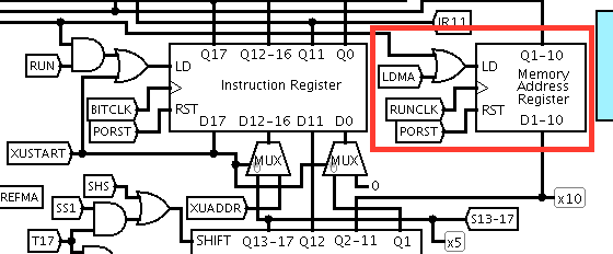
A quirk of this approach is that the value to be loaded into the PC
needs to be set into switches 2 to 11, not 1 to 10 as might have been
expected. This is due to the fact that IR/MA is loaded with an
instruction during T17 of a fetch cycle, at which time the final shift
of the value in the S register has not yet been performed; to
compensate for this, inputs 0 to 16 of IR/MA are wired to outputs 1 to
17 of the S register.
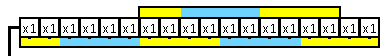
This is not really a problem, it's just a matter of labelling the
switches appropriately. I created a bezel for the switches on the main
schematic showing where the hex digits go for PC values and data.
Load Address Microcode
# MISC values
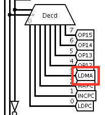
LDMA = 1101 # Load MA register from S register
# Load Address
1 00001 0 0000 : - - -- --- - -- - - -- - - - - - - PLS - --- PISW -- # Load switches into S
1 00001 0 0001 : - - -- --- - -- - - -- - - - - - - LDMA - --- ---- # Load MA from S
1 00001 0 0010 : - - -- --- - -- - - -- - - - - - - LDPC - --- ---- # Load PC from MA
1 00001 0 0011 : - EOI -- --- - -- - - -- - - - - - - HALT - --- ---- # Stop